Calibration
The Printalyzer Densitometer uses components that should provide stable readings over the lifetime of the device. However, to ensure measurement accuracy, calibration should be checked periodically.
A transmission step wedge, and a reflection step tablet, have been provided with the device for the purpose of performing and verifying calibration. These materials must be kept clean and should be stored in their envelopes when not in use. The basic layout of these materials, and their expected measurement locations, can be seen in Fig. 3.
Note: The read head must be firmly held down during all measurements to ensure accurate results. If the head is released during the process, calibration will fail.
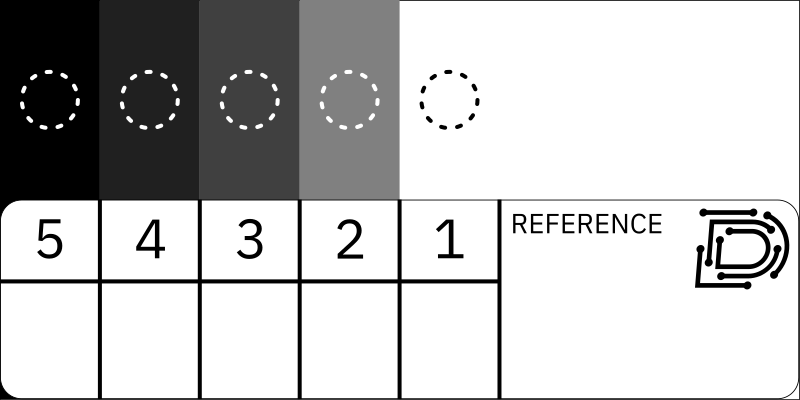
Fig. 3 Calibration strip layout, showing measurement locations
Reflection Calibration
Press the [

 ] buttons together to open the device menu
Select “
Calibration” and press
Select “
Reflection” and pressMake sure that the numbers after “
CAL-LO” and “CAL-HI” match the corresponding numbers on the provided reflection step tablet’s labelIf either of these numbers do not match, then adjust them accordingly
Select with
Adjust the value with
and Accept with
Select “
** Measure **” and pressFollow the on-screen instructions:
Position the center of the reflection step tablet’s CAL-LO patch in the read area, firmly hold down the sensor head
 , and press the button
Position the center of the reflection step tablet’s CAL-HI patch in the read area, firmly hold down the sensor head
, and press the button
If using 3rd party calibration materials, the following guidance should be taken into account:
The CAL-LO patch should have a marked density of
0.10or less.The CAL-HI patch should have a marked density roughly within the range of
1.50through1.90.If the material was marked for color densitometer calibration, then use the values labeled as “visual” or “black.”
The material must be held perfectly flat against the bottom of the sensor head to ensure accurate measurement. This is easy if the material is made from photographic paper, however it can be quite difficult if the material is made from a thick piece of painted metal.
Transmission Calibration
Press the [
] buttons together to open the device menuSelect “
Calibration” and pressSelect “
Transmission” and pressMake sure that the number after “
CAL-HI” matches the corresponding number on the provided transmission step wedge’s labelIf the number does not match, then adjust it accordingly
Select with
Adjust the value with
and Accept with
Select “
** Measure **” and pressFollow the on-screen instructions:
With the read area empty, firmly hold down the sensor head
and press the buttonPosition the center of the transmission step wedge’s CAL-HI patch in the read area, firmly hold down the sensor head
, and press the button
If using 3rd party calibration materials, the following guidance should be taken into account:
The CAL-HI patch should have a marked density roughly within the range of
2.90through3.00.If the material was marked for color densitometer calibration, then use the values labeled as “visual” or “black.”
The material must be measured with the emulsion side facing upward towards the sensor. Whether or not the material is labeled this way may depend on the design of the densitometer it was originally intended for use with.
Measurement Light
Measurement light calibration is a process normally performed as part of device assembly. As it should not normally need to be repeated by the user, the desktop companion software is required to perform it.
The purpose of measurement light calibration is to determine the optimal brightness of the device’s light sources for measuring density targets. This is necessary because manufacturing variation in several components can lead to significant device-to-device differences in measurement light output. If these differences are too great, then target calibration alone cannot easily compensate for them.
The process of actually performing measurement light calibration involves the desktop software and is currently beyond the scope of this manual.
Sensor Gain
Sensor gain calibration is a process normally performed as part of device assembly. As it should not normally need to be repeated by the user, the desktop companion software is required to perform it.
The purpose of sensor gain calibration is to determine the actual relationship between the various gain settings of the light sensor used by the device. This is necessary so that target readings taken at different levels of sensitivity can be accurately compared.
Sensor gain calibration is discussed in more detail in the Theory of Operation section, later in this manual. The process of actually performing sensor gain calibration involves the desktop software and is currently beyond the scope of this manual.
Sensor Slope
Sensor slope calibration is a process normally performed as part of device assembly. As it should not normally need to be repeated by the user, the desktop companion software is required to perform it.
The purpose of sensor slope calibration is to compensate for a slight non-linearity in the sensor’s response curve. This is necessary to ensure accurate readings at both low and high densities, while still only requiring two points to be measured as part of the user calibration process described above.
Sensor slope calibration is discussed in more detail in the Theory of Operation section, later in this manual. The process of actually performing sensor slope calibration involves the desktop software and is currently beyond the scope of this manual.