Maintenance
Cleaning
Whenever required, the device may be wiped clean with a lint-free cloth. The sensor head may be cleaned by lightly blowing compressed air into its openings.
Do not attempt to clean the device with alcohol or any solvent cleaners.
Updating Firmware
The Printalyzer Densitometer is designed to have firmware that can be updated. This is so that features can be added, and bugs can be fixed, after the device has shipped. The update process is designed to be as easy as possible, and can be performed from any computer that the device can be plugged into.
To update the device firmware, you will need:
The Printalyzer Densitometer itself
The latest firmware file, downloaded to your computer (a file with a name similar to
densitometer.uf2).A cable that can connect from a USB port on your computer to the port on the Printalyzer Densitometer

Fig. 5 Starting the bootloader
The update procedure is as follows:
Make sure the USB cable is plugged into your computer, but not the device.
While simultaneously holding down the sensor head
 , and pressing the
  and
and  buttons, plug the cable into the device.
The device should now start in a special mode, with a USB logo displayed on the screen.
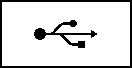
Fig. 6 Device in bootloader mode
You may now let go of the device.
On your computer, a USB disk volume named “PRDENSBOOT” should appear.
Copy the firmware file (e.g.
densitometer.uf2) to the “PRDENSBOOT” device,While the firmware is being copied, you should see a progress indicator on the device.

Fig. 7 Device receiving updated firmware
Once complete, the device should automatically reset and start up with the new firmware. If it does not reset correctly, simply unplug it and plug it in again to restart it.
Updating the Bootloader
It is also possible to update the bootloader itself, which is the special piece of software that enables the user-friendly update process described above. Updates to the bootloader are expected to be infrequent, and should only be necessary to fix issues that prevent the normal update process from functioning correctly.
To update the device bootloader, you will need:
The Printalyzer Device itself
The latest bootloader file, downloaded to your computer (a file with a name similar to
densitometer-bootloader.dfu).A cable that can connect from a USB port on your computer to the port on the Printalyzer Densitometer
A small pin, such as a bent paperclip
A special piece of software called dfu-util (http://dfu-util.sourceforge.net/)
The dfu-util website has downloadable binaries and instructions for Windows, macOS, and Linux.
Alternative USB DFU utilities, such as STM32CubeProgrammer (https://www.st.com/en/development-tools/stm32cubeprog.html) can also be used. However, they will not be covered by these instructions.

Fig. 8 Updating the bootloader
The bootloader update procedure is as follows:
Make sure the USB cable is plugged into your computer, but not the device.
Insert the pin into the tiny hole on the back side of the device. Inside the hole there is a tiny button, which you should press with the pin. It may be hard to feel, so be gentile.
While using the pin to hold the internal button down, plug the USB cable into the device.
The device should now start, but the display will remain blank. On Windows, you may notice the computer detecting a new USB device. On macOS or Linux, you are unlikely to notice anything unless you are looking at USB utilities or log files.
You may now let go of the device.
If you run the command
dfu-util -l, you should now see several entries returned with the ID of[0483:df11]
To install the bootloader, run the following command:
dfu-util -a 0 --dfuse-address 0x08000000 -D densitometer-bootloader.dfu
(Note: Newer versions of dfu-util may no longer require the address argument.)
Once the update procedure is complete, you will need to unplug the device and plug it back in to reset it. If the main firmware is valid, then it will be started. If the main firmware is corrupted, then the bootloader (as described above) will automatically start.
Troubleshooting
The device hinge feels too loose or too tight
The hinge mechanism is designed to allow for free up-and-down motion, aided by a set of springs, and to lock into place when taking measurements. This is necessary to allow for ease of operation, while ensuring repeatable alignment with the transmission light.
Normally, a set of screws on either side of the hinge keep it generally stable, while groves near the middle provide some extra tension for stability when closing the device. However, due to manufacturing tolerances or wear, it is possible that this mechanism may need adjustment.
To adjust the hinge, use a 2mm sized hex driver. Both sides should be tightened as equally as possible, right up until the point where the hinge ceases to open smoothly. Once getting to that point, carefully back out the screws no more than a quarter turn at a time until the hinge moves smoothly again.
Note: These screws are not designed for repeated adjustment after initial device assembly, as doing so could strip or weaken the threads inside the device. As such, this process should be performed as sparingly as possible.
The device displays “Sensor initialization failed” on startup
This means that the device’s processor was unable to communicate with the light sensor used for density measurements. Please contact Dektronics about sending the device back for service or replacement.
The device displays “Invalid calibration” when taking a measurement
It is possible that the device’s calibration data has become corrupted. To fix, it is recommended that you attempt to perform the target Calibration process. If that still does not fix the issue, then use the desktop software to check device calibration numbers and re-run gain or slope calibration if necessary before trying target calibration again.
Note: The Quick Start Guide included with the device should include a label on its last page with the factory calibration numbers for your device. This can be used, in combination with the desktop software, to restore the initial calibration of your device.
The device displays “Sensor read error” when taking a measurement
Message is shown after all measurements
It is possible that there is a problem with the sensor or device. Please use the desktop software to check device light and gain calibration numbers if possible. If those appear normal, then please contact Dektronics for advice.
Message is shown only on some measurements
It is possible that there is either a problem with the device firmware, or with the light and gain calibration. Please use the desktop software to check device light and gain calibration numbers if possible. If those appear normal, then please contact Dektronics for advice. When contacting Dektronics, please provide as much detail as possible about what material(s) cause this error during measurement.
Message is shown only when taking a transmission measurement with no film under the sensor
The most likely cause of this error is incorrect light calibration, possibly caused by a hinge alignment issue. If adjusting the hinge (see above) does not resolve it, then use the desktop software to run the gain calibration process. This will automatically calibrate both the measurement light and the sensor gain, as part of a combined sequence.